Oct 15, 2019

Quantizer

To help the modular system play in musical tune, I decided I wanted a Quantizer module. After significantly longer development time than I anticipated, the result is this two-channel Quantizer in 10hp Eurorack format.

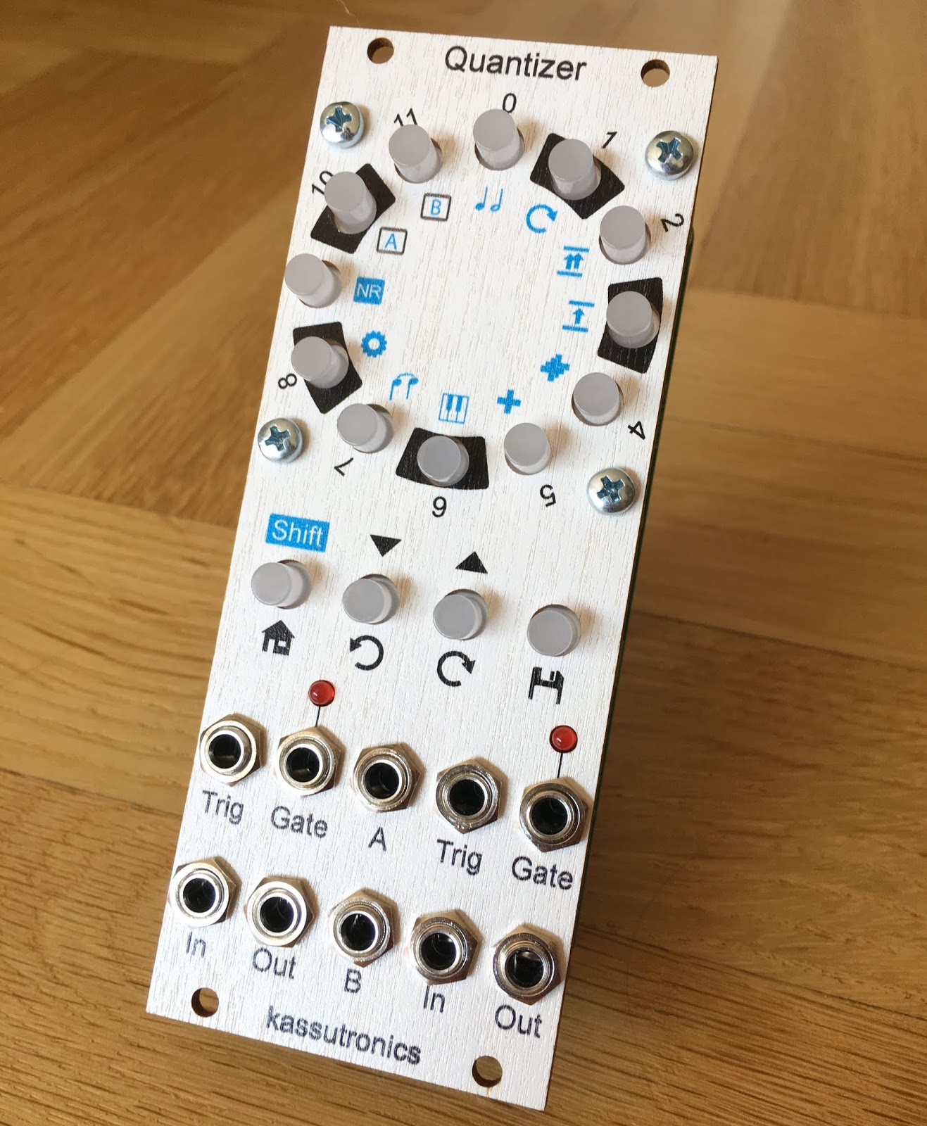
Quantizer module with printed wooden front panel


In its simplest form, a quantizer is a module that takes in a control voltage, and outputs the same voltage rounded to the nearest note. In the usual V/Oct tuning system, and assuming we use just tuning, that means rounding to the nearest 1/12th of a Volt.

An obvious extension to such a basic quantizer is to have adjustable scales, where some of the 12 notes are disabled and hence will never be output. For example a quantizer could be set to a major scale to make sure the VCOs will always play only notes from that scale.

In my Quantizer I chose to have completely flexile scales, defined by 12 illuminated push buttons that are toggled on and off by pressing them. This allows any custom scale to be programmed, or for example only a subset of a scale to get more control over the resulting music. I often find enabling only 3 or 4 notes gives more useful results than a traditional 7-tone scale.

User interface

Rather than the traditional piano keyboard layout, I ended up with a circular layout of the scale buttons that is comparable to the concept of bracelets. This layout is to me more intuitive compared to the piano keyboard - for example transposing the scale is just rotating the notes on the ring. As shown below, on the front panel layout I still made shaded regions to indicated the black keys on the piano keyboard for reference.

Front panel layout

Below the scale buttons are function buttons, including two buttons to rotate the scale clockwise or counterclockwise, allowing one to easily change the key. Using the shift button in combination with the scale buttons more advanced options can be changed, such as different variations on transposing one or both channels. The operation of all functions is explained in detail in the user manual.

Each of the two quantizer channels has obviously an input and output jack. The Gate output (and corresponding LED) go high whenever a new note is quantized, and can be used for example to trigger envelopes. Finally, each channel has a Trig input, which can optionally be used to trigger the quantization at desired times. When nothing is connected to the Trig input, the quantizer goes to a new note whenever the input voltage changes to the next note.

Finally there are two assignable CV inputs A and B. In my first prototype these inputs were absent, but after playing with rotations and transpositions for a few minutes it became blatently obvious that these functions should be sequenceable with CV. The CV inputs can be assigned to almost all functions, such as changing key, transposing one or both channels, adjusting gate lenght or even loading a completely different scale from memory.

Hardware design

Quantization is inherently a digital operation, and it is no surprise that this module is implemented digitally. While quantizers made up of only discrete logic chips exist (notably Ray Wilson's MFOS Voltage Quantizer), a microcontroller makes the implementation both a lot simpler and more flexible. The venerable ATMega328P is a good match for the complexity of this project, and makes the Quantizer programmable in the Arduino IDE which hopefully lowers the barrier to firmware development if anyone is interested in that.

A key component of a quantizer is a digital-to-analog converter (DAC), which should be highly linear to ensure all quantized notes are in tune. Rather than a fancy DAC chip I went with filtered pulse-width modulation (PWM). While PWM has limitations, it gives excellent linearity since the output voltage steps are derived from the accurate timing of the crystal oscillator. Filtering the PWM signal properly is challenging, but using a 4th order buffered passive filter the results were satisfactory.


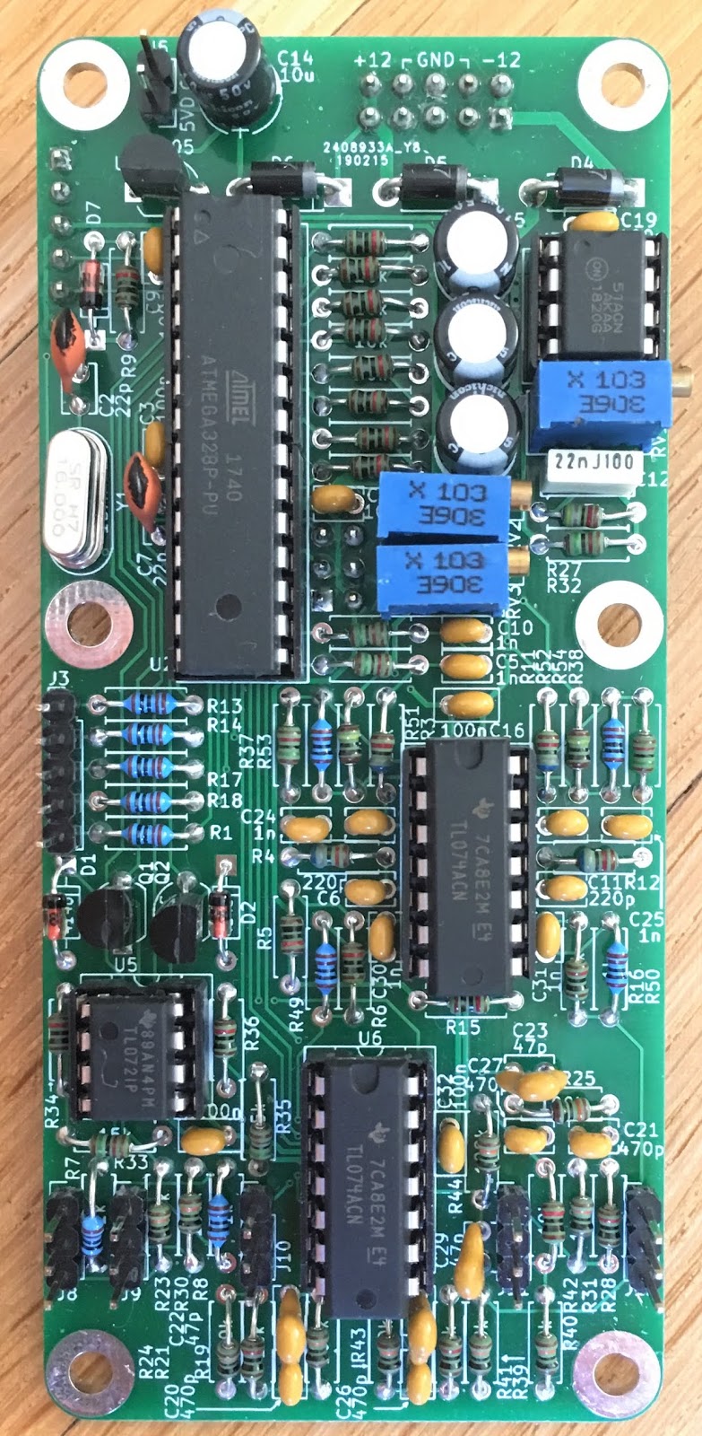
A more detailed description of the hardware as well as schematics are available in the build document. The hardware part of this module is not open source, but like with my other designs personal, non-commercial use is allowed.

Software design

The firmware of the Quantizer is written in the Arduino IDE, and made available open-source such that anyone can make modifications or alternatives if desired. Due to the limited resources on the 8-bit microcontroller, hardware and software are fairly tightly knit together. If you fancy developing the firmware for this module, the comments in the code give the best starting point. Also feel free to get in touch, I am happy to help where I can.

Building the Quantizer

Are you intersted in a Quantizer for your own system? I recommend first reading the user manual to see if the Quantizer fits your needs, and then have a look at the build document for building information.

I offer PCBs and front panels for sale, and generally also pre-programmed microcontroller chips if you don't fancy programming it yourself. The build involves a few 0805 and SOIC-size SMD components, but is mostly through-hole. While the component count is high compared to my other modules, there is nothing particularly difficult in the build.

All documentation can be found on Github.

Demo

The short demo video below demonstrates some of the Quantizer features. The Beatstep Pro drives a slow 4-note sequence which is fed to the CV A input and set to change the Rotation of the Quantizer. This creates a simple chord progression.

The melody voice comes from Quantizer channel 1. It's input is a free-running LFO, and the trigger is provided by a second channel of the Beatstep Pro. This combination creates quantized pseudo-random melodies, which follow the key of the chord progression.

The chords are made up by two VCOs. One comes from channel 2 of the Quantizer, also fed by the same LFO, but triggered only on quarter notes. The second VCO plays the root note directly from the Beatstep Pro.


Channel 37 did a great review and build video of the Quantizer:


36 comments:

  1. Would good add short video (or not short), if it not difficult.

    ReplyDelete
  2. Awesome.. after skimming through the documents.. Jaw droppingly awesome!

    ReplyDelete
  3. Is there any way to get the LEDs to flash in the pitch that is happening? Kind of like the uScales does.

    BTW I love the module!

    ReplyDelete
    Replies
    1. Something like this could be implemented. The LEDs are not PWMed (to avoid possible interference), so they can't flash brighter, but they could for example flash off briefly.

      Delete
    2. This is a great idea.

      Delete
  4. This looks great. Would it ever be possible to purchase a kit?

    ReplyDelete
    Replies
    1. Hi! Both Thonk and Synthcube are working on kits for this module. I don't know when they will come out, best ask from the stores directly.

      Delete
  5. Nice! I really like the trig-in kinda s&holding on incoming pitch cv function and the freely assignable a/b inputs (chord progression/key change).
    One question: 2 voices would be a little limiting in my setup; is there a way to have two quantizers (4 channels) working together sharing the same scale settings/ chord progression infos coming from one a/b cv in without having to program each quantizer/synch them?
    Thanks and big ups for this awesome piece of work!

    ReplyDelete
  6. The two color switches are sold out.
    Do I miss anything by getting a single color version?

    ReplyDelete
    Replies
    1. Hi! The Quantizer uses normally single color switches, so that's fine! Dual color switches work also as a backup (only one color is used).

      Some videos show a mix of red and green switches, since I did not have enough of any single color during prototype development

      Delete
    2. Thanks for the super fast reply.

      I will then order the color of my choice. Too bad TME doesn't seem to have any of them in stock, except for the silver ones.

      Delete
  7. Hello Caspar,

    I'm wondering if microtonal scales could be somehow implemented. As this is based on coding, maybe it could work?

    thx
    N.

    ReplyDelete
    Replies
    1. Hi! The voltage output is based on PWM where 1 lsb change of the output is exactly 1/12 of a volt. This provides very good linearity (hence easy calibration), but does not allow for microtonal scales.

      Delete
    2. Hi and thanks for the answer!
      I'll keep enjoying it as it is ;)

      Delete
  8. Hi Caspar, is the code available to flash my own controller?

    Thanks
    Reuben

    ReplyDelete
    Replies
    1. Yes!
      Code: https://github.com/kassu/KassutronicsQuantizer
      Compiled binaries: https://github.com/kassu/KassutronicsQuantizer/releases

      Delete
    2. Thank you! On another note, can you tell me what type/part number the switches are? I know Thonk carries them now, but was hoping to find them locally here in the States at Mouser, Digikey, Tayda, etc.

      Thanks again!

      Delete
    3. There are a few links and part numbers for them on the Part Sourcing page: https://kassu2000.blogspot.com/p/common-parts-list.html

      Delete
    4. Hmm... all I see are the SPDT sub-miniature toggle switch links. Is there something I'm missing?

      Delete
    5. You are right, I replied without thinking. For the quantizer pushbuttons the only known sources are TME and Thonk. Both ship to US fortunately

      Delete
    6. No worries. Thanks again!

      Delete
  9. Hi Casper,
    Sorry for the bother but I’m having difficulty with my build and hoping you might be able to help.
    I’ve built the unit (got the right check voltages, reprogrammed my microcontroller) but on power up, all the led buttons light up and nothing else happens (even when I press other buttons).
    Any advice?

    ReplyDelete
    Replies
    1. Hi! Did you already make any progress with this? I think we should first narrow down if the problem comes from the user interface (LED push buttons), or if the microcontroller is running at all.

      One place to start looking is if the actual quantizing works. So if you feed it with some voltages, do you get something on the output?

      If that works, the problem would likely be in the control of the push buttons. These are controlled by the four SMD shift register chips (74HC595 and 74HC165), or the signals going through them.

      If nothing works at all, you could probe the microcontroller crystal pins to see if it is at least making a clock. This requires a good oscilloscope, there should be a 16MHz signal on those.

      Delete
    2. So, not to thread jack, but I built two of these, one works perfectly, the other has the same behaviour as Artois' module. All lights on, buttons seemingly don't respond to presses. However, I can further advise that it DOES take an input from a MTM turing machine and puts out quantized stepped CV on of both channels - so it is partly working. But button presses won't rotate the bracelet, note select, enter the shift modes.

      I initially suspected the issue was on the front panel pcb, so I swapped on the known working front panel from the other module, but the problem persisted. I can confirm that the front panel from the problem module works normally on the main pcb from the working module. So that suggests to me that the issue is on the Main PCB, notwithstanding that it is quantizing. Hoping we can work together to solve the issue here publicly so perhaps it will help others - or should I post to Kassutronics Quantizer modwiggler thread (or somewhere else?) Thanks! :)

      Delete
    3. Hi! Since in this case the front panel PCB seems working, the culprit should be somewhere in the control lines for the LEDs on the main PCB. I think there are basically three options:
      - One of the resistors R1, R13, R14, R17, R18 could be the wrong value or have a connection issue
      - The microcontroller itself could have a bad pin (bad connection or internally broken)
      - The connector J3 could have an issue

      Perhaps the easiest things to test are:
      - Test what happens if you swap the microcontrollers between your two modules
      - Measure the 5 lines from J3 to the microcontroller, they should all have 1k resistance due to the series resistors

      I hope this helps, let me know if you need further assistance!

      Delete
  10. Hello Casper,

    since the LP2951Acm isn a Aula me at he moment, can I use the CM version instead? This one is a little less accurate, I guess. But is this any crucial for your quantizer to work correctly?

    Thanks
    wotar

    ReplyDelete
    Replies
    1. shitty typo’s… 😅

      „LP2951ACM isn‘t available at the moment“

      …makes more sense

      Delete
    2. LP2951CN should be fine. Note that CM is a SOIC package, and you need the PDIP version to fit the PCB

      Delete
    3. Great! And yes, of course you're right about the package. I already realised that I confused that M'n'N thing. LP295CN in fact is the one I was talking about.

      Thank you :)

      Delete
  11. Hi Casper, I am missing the 1 5k trimmer potentiometer from the BOM and note from the photos of the completed main pcb that you have used 3 x 10k trimmers. Would i be able to substitute the 5k with a 10k i have in stock without too much trouble? Thanks.

    ReplyDelete
  12. Hi Casper. I've noticed that D6 is missing on my Thonk kit and that it is also missing in the photo on their build notes (https://www.thonk.co.uk/wp-content/uploads/2023/09/kassu-quantizer-thonk-build-notes.pdf). Can I assume that this is okay to be left unpopulated ?? thanks !

    ReplyDelete
    Replies
    1. Hi! Yes, D6 is unpopulated on purpose. I still have to update this in the docs, apologies for the confusion

      Delete
    2. This just saved me a massive headache. I also noticed the unpopulated D6 and didn't dare hook it ito the case yet. I was already looking into hacking in an equivalent THT component.

      Delete
    3. Fortunately you found it then. By now the build doc is also updated with info about D6 :)

      Delete